CNC Milling: Revolutionizing Precision Manufacturing with Automated Efficiency
CNC milling, powered by computer numerical control (CNC), stands at the forefront of modern manufacturing, revolutionizing the production of intricate and precisely engineered components. This subtractive manufacturing process relies on automated multi-point cutting tools to meticulously remove material from a workpiece. Going beyond the limitations of traditional manual milling, CNC milling offers the creation of complex geometries with unparalleled precision and repeatability. The journey from concept to finished product involves a detailed series of steps, including model generation, CAM programming, machine setup, milling execution, and finishing. As we delve into the processes and types of CNC milling, it becomes evident that this technology has become indispensable in the manufacturing landscape, providing engineers and manufacturers with a powerful tool to streamline production processes and deliver high-quality, precise products across diverse industries.
What is CNC Milling?
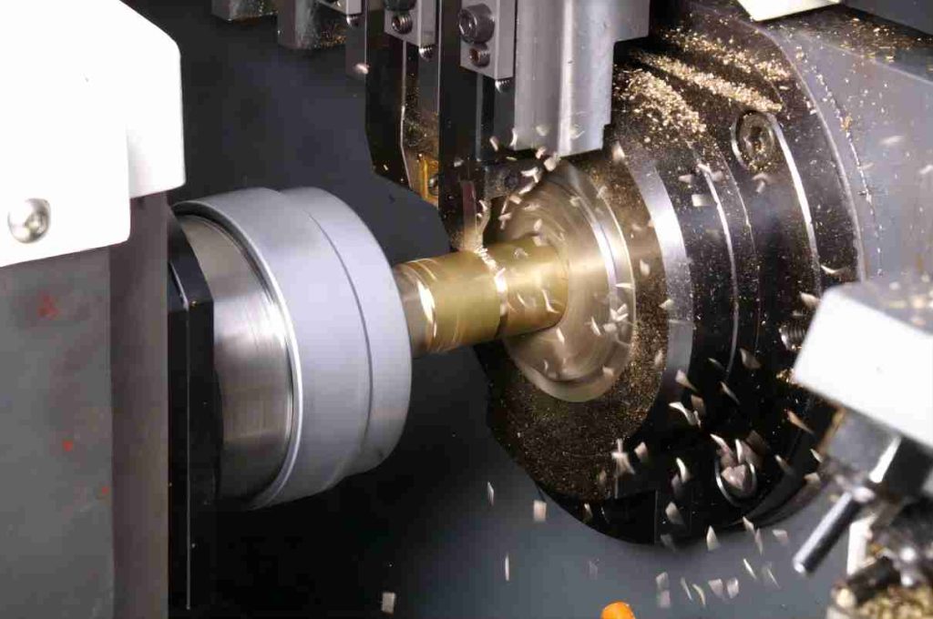
CNC milling is a subtractive manufacturing process employing computer numerical control (CNC) to automate the removal of material from a workpiece via precisely controlled multi-point cutting tools. This automated approach enables the creation of complex geometries and intricate features with high precision and repeatability, exceeding the capabilities of traditional manual milling methods.
What Are the Processes of CNC Milling?
The CNC milling process is a multi-stage procedure involving meticulous planning, programming, and machine execution to transform raw material into the desired finished product. Here’s a detailed breakdown of the key steps:
1. Model Generation
- CAD Software: The initial stage involves conceptualizing and defining the desired part geometry using a computer-aided design (CAD) software. This software allows for precise specification of dimensions, tolerances, surface finishes, and internal features.
- 3D Modeling: The CAD software environment facilitates the creation of a 3D model of the part, accurately representing its shape, size, and internal cavities (if any). This virtual model serves as the blueprint for the CNC machining process.
- Design Validation: Once the 3D model is complete, thorough validation is crucial. This may involve virtual simulations of the machining process to identify potential toolpath collisions or areas requiring optimization for efficient material removal.
2. CAM Programming
- Software Interface: The validated CAD model is then imported into computer-aided manufacturing (CAM) software. This software acts as a translator, converting the geometric data into a series of machine instructions understood by the CNC milling machine.
- Toolpath Generation: The CAM software utilizes the CAD model to define the toolpath, which specifies the precise trajectory of the cutting tool as it removes material from the workpiece. This involves defining the starting and ending points, feed rates, spindle speeds, and dwell times for each segment of the machining process.
- G-code and M-code Generation: The CAM software translates the toolpath and additional machining parameters into G-code and M-code instructions. G-code commands specify the tool movement and cutting parameters, while M-code commands control auxiliary functions like coolant activation, tool changes, and spindle orientation.
3. Machine Setup and Program Loading
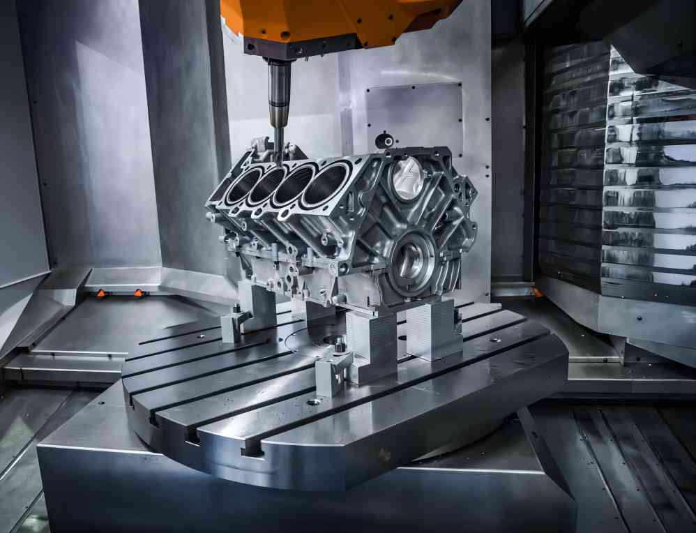
- Workpiece Preparation: The chosen raw material, duly secured to the machine’s worktable, serves as the starting point for the machining process. This workpiece is carefully positioned and aligned based on the programmed toolpath and datums defined in the CAM software.
- Tool Selection and Installation: The appropriate cutting tool, chosen based on the desired features and material being machined, is mounted onto the spindle of the CNC milling machine. Tool offset values, accounting for the tool’s geometry and wear, are carefully calibrated to ensure accurate machining.
- Program Loading and Verification: The generated G-code and M-code programs are uploaded onto the CNC machine’s control system. A dry run simulation may be performed to verify the program and identify any potential errors before initiating the actual machining process.
4. Milling Execution and Monitoring
- Automatic Control: Once activated, the CNC machine meticulously follows the programmed toolpath, executing the cutting movements, spindle speeds, and feed rates with high precision. The machine’s control system continuously monitors the process and adjusts parameters as needed based on sensor feedback.
- Material Removal: The cutting tool, rotating at high speeds, gradually removes material from the workpiece according to the programmed path. Chip formation and coolant application are carefully managed to ensure efficient machining and optimal surface quality.
- Process Monitoring: Throughout the milling process, the operator closely monitors the machine’s performance and workpiece condition. Visual inspection, along with sensor data and audible cues, provide valuable insights into the progress and potential issues that may require intervention.
5. Finishing and Inspection
- Post-processing: Upon completion of the rough machining, the part may undergo additional finishing steps depending on the desired surface quality. This may involve deburring, polishing, or other techniques to remove imperfections and achieve the specified finish.
- Dimensional Accuracy: The final stage involves a thorough inspection of the machined part to verify its dimensional accuracy and conformance to the original CAD design. Coordinate measuring machines (CMMs) or other precision instruments are often used for this purpose.
- Quality Assurance: The inspection data is compared against the design specifications to ensure the part meets all functional and aesthetic requirements. This final quality assurance step ensures the consistency and reliability of the CNC milling process.
What Are the Types of CNC Milling?
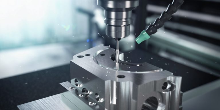
While CNC milling encompasses a broad spectrum of methodologies, four fundamental techniques form the cornerstones of this versatile manufacturing process. Each of these techniques utilizes specific toolpath strategies and cutting geometries to achieve distinct machining objectives:
1. Face Milling
- Operation: Face milling employs flat-bottomed end mills or face mills to create planar surfaces perpendicular to the spindle axis. This technique excels at achieving high surface quality and flatness on large areas.
- Typical Applications: Flattening faces on blocks, plates, and flanges, machining bearing surfaces, and creating datum planes for subsequent machining operations.
- Tool Selection: Flat-bottomed end mills with varying diameters and flute counts are chosen based on the desired material removal rate, surface finish, and workpiece accessibility.
- Programmatic Considerations: Toolpath planning involves straight-line passes at consistent depths across the entire surface, ensuring even material removal and minimizing tool contact time. Feed rate optimization plays a crucial role in balancing surface finish and machining efficiency.
2. Planing
- Operation: Planing utilizes rotating milling cutters with teeth on their periphery to remove material from flat surfaces parallel to the spindle axis. This technique is ideal for achieving high accuracy and dimensional control on large planar regions.
- Typical Applications: Surfacing large plates and blocks, leveling uneven surfaces, and preparing workpieces for subsequent machining.
- Tool Selection: Planing mills, with varying widths and tooth profiles, are chosen based on the desired material removal rate, surface finish requirements, and machine rigidity.
- Programmatic Considerations: Toolpath planning typically involves overlapping passes with precise depth increments. Feed rate and cutting depth optimization are crucial for balancing productivity and surface quality.
3. Angle Milling
- Operation: Angle milling employs cutters with angled cutting edges to machine inclined surfaces or features like chamfers and grooves. This technique offers versatility for creating angled profiles and intricate geometries.
- Typical Applications: Creating chamfers on edges, machining dovetail joints, and forming grooves for keyways or seals.
- Tool Selection: End mills with specific flute angles and geometries are chosen based on the desired angle of the feature, material requirements, and chip evacuation needs.
- Programmatic Considerations: Toolpath planning necessitates meticulous control of the tool axis path relative to the workpiece surface. Precise angular positioning and control of cutting depths are crucial for achieving accurate and consistent features.
4. Contour Milling
- Operation: Contour milling utilizes specially shaped tools to machine complex curved surfaces and intricate profiles. This technique offers the highest level of flexibility for creating diverse geometric features.
- Typical Applications: Machining curved surfaces on molds, dies, and prototypes, creating intricate profiles for aerospace components, and crafting decorative features on finished products.
- Tool Selection: Ball nose mills, bullnose mills, and profile cutters with varying radii and geometries are chosen based on the complexity of the contour, material characteristics, and desired surface finish.
- Programmatic Considerations: Toolpath planning requires the meticulous generation of smooth spline curves that accurately follow the desired contour. Five-axis CNC machines may be employed for machining complex 3D profiles.
Conclusion
CNC milling has become an essential technology in modern manufacturing, enabling the efficient production of high-precision, complex parts for various industries. Its versatility, automation capabilities, and inherent accuracy make it a valuable tool for engineers and manufacturers seeking to optimize their production processes and deliver high-quality products.

